Table of Contents
Hydraulic Brake :
Construction and Working of Hydraulic Brakes


The master cylinder is connected to all the four-wheel cylinders by tubing or piping. All cylinders and tubes are fitted with a fluid that acts as a link to transmit pedal force from the master cylinder to wheel cylinders. Brake Fluid The fluid-filled in the hydraulic brake system is known as brake fluid. It is a mixture of glycerine and alcohol or castor oil and some additives. The Master cylinder consists of a piston that is connected to peal through the connecting rod. The wheel cylinder consists of two pistons between which fluid is filled. Each wheel brake consists of a cylinder brake drum. This drum is mounted on the inner side of the wheel. The drum revolves with the wheel. Two brake shoes that are mounted inside the drum remain stationary. Heat and wear resistant brake linings are fitted on the surface of the brake shoes.
Working of Hydraulic Brakes
Working of master cylinder of Hydraulic brake:
Method of Bleeding of hydraulic brakes:
2) Manual Bleeding
3) Gravity bleeding
When the bleeder screw is opened, the pressure force air and brake fluid out of the bleeder screw. With a pressure bleeder, you can bleed the hydraulic system without any helper. The pressure used in pressure is usually 104 to 138 KPa.

b) Loosen the bleeder screw at least one full turn.
c) Have an assistant to depress and hold the brake pedal and then tighten the bleeder screw.
d) Have your assistant to release the brake pedal.
e) Repeat steps b,c & d until the fluid flow in the container is free of air bubbles. Periodically check the brake fluid level in the master cylinder and brake fluid of correct grading to keep the reservoir filled.
f) Repeat this procedure at each wheel.

3) Gravity bleeding:
Gravity bleeding is the method of bleeding that uses the earth’s gravity to bleed air from the hydraulic system. No external force is applied to brake fluid. To bleed the system following procedure is adopted.
a) At the wheel, the cylinder loose the bleeder screw at least one full turn.
b) Remove the cover from the master cylinder reservoir. The level of brake fluid to flow from the bleeder screw.
c) Watch the bleeder hose when brake fluid flows from opening and tightening the screw.
d) Repeat this procedure at each wheel in sequence and it should be changed.
Types of Hydraulic Braking System :
The hydraulic braking scheme is categorized as,
1. Based on the frictional contact system, there are two kinds of hydraulic pumps–
(i)drum brake or inner hydraulic valve expansion.
(ii) Hydraulic disk brakes or internal hydraulic brakes.
2. Based on the brake force allocation-there are two kinds of hydraulic brakes-
(i) single-acting hydraulic pumps
(ii)dual-acting hydraulic pumps
Hydraulic Disc Brake:
Construction of Hydraulic Disc Brake :
A disc brake consists of a rotating disc and two friction pads that are actuated by a hydraulic braking system. The friction pads remain free on each side of the disc when brakes are no applied. They rub against the disc when brakes are applied to stop the vehicle.

Working of Hydraulic Disc Brake :
In a disc brake, the fluid from the master cylinder is forced into a caliper where it presses against a piston. The piston in turn crushes two brake pads against the disc that is being attached to the wheel, making it to stop or slow down. The main advantage of disc brakes is their resistance to wear as the discs remain cool even after repeated brake applications.
Difference between Mechanical Braking System and Hydraulic Braking System
| Sr. no. | Mechanical Braking System | Hydraulic Braking System |
|---|---|---|
| 1. | Less Braking efficiency. | More Braking Efficiency. |
| 2. | Poor Anti fade characteristics | Better Anti-fade characteristics |
| 3. | Complicated due to more parts. | Simple in construction |
| 4. | It do no self compensate | Self-compensating system |
| 5. | Construction is less flexible | Construction is more flexible |
| 6. | Low mechanical advantage | High mechanical advantage |
| 7. | External Lubrication is required | System is self-lubricating |
| 8. | No leakage problem | Leakage may take place |
| 9. | No hydraulic oil use | Hydraulic oil is used |
| 10. | More effort required for braking operation | Less effort required for braking operation |
| 11. | Cheaper | Expensive |
| 12. | Ex: Motor Cycles | Ex: Cars and Jeeps. |
Difference between Hydraulic and Pneumatic Braking System:
Hydraulic vs Pneumatic braking System – Comparison between Hydraulic and Pneumatic Braking System
| Sr. no. | Hydraulic Braking System | Pneumatic Braking System |
|---|---|---|
| 1. | Braking Fluid used as a working medium | Compressed air is used as a working medium |
| 2. | Simple in construction & less expensive. | Complicated in construction and expensive. |
| 3. | Occupied less space as compared to Air brake | Occupied more space as compared to Hydraulic brake |
| 4. | The system is self-lubricating | Need to lubricate mechanical parts |
| 5. | Bleeding is necessary | No need for bleeding |
| 6. | The increased braking effort, but less powerful than air brakes. | Most powerful than Hydraulic brake |
| 7. | Low maintenance cost | Maintenance cost is more |
| 8. | Mostly used in passenger cars, LMVs | Mostly used in heavy vehicles like buses and trucks. |
Advantages and Disadvantages of Hydraulic Braking System :
Hydraulic Braking System has some advantages and limitations over other Braking System i.e. Mechanical, Pneumatic braking System ;
Advantages of Hydraulic Braking System :
The advantages of the hydraulic braking system are as follows,
Disadvantages of Hydraulic Braking System :
Disadvantages of the hydraulic braking system are as follows,
See Also: Working Of Pneumatic /Air Braking System 
Related posts:
 Brake Master Cylinder – Function , Working , main parts and Diagram
  Air Brake System – Parts, Working, Diagram, Principle, Advantages
  Types of Brakes | Different types of Braking System
  Braking System : Function , Classification ,Electronics Brakes
 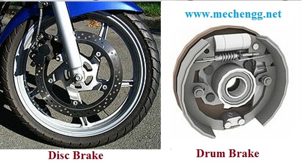 Introduction To Brakes and Different Types Of Brake | Function Of Braking System
  Master Cylinder | Types , Working Principles and Applications
  Introduction to Automobile Braking System- Types Of Brakes
  Hydraulic Circuit (System) – Parts, Application, Advantages, Disadvantages
4 thoughts on “Hydraulic Brakes – Parts, Working, Diagram, Advantages and Disadvantages”
Leave a Reply
Recent Posts
Mechanical Engineering is an essential discipline of engineering encompassing many specializations, with each contributing its unique aspect to the dynamic and inventive nature of this field. With...
The Ram Lalla idol, which is installed at Ayodhya's Ram temple has many significant religious symbols from Hinduism. All 10 incarnations of Lord Vishnu are engraved on the idol. Notably, Lord Ram is...
Good notes
This content helped me so much in making my project so DIL SE THANK YOU.
Am asking for the PDF of this good notes
Good day Sachin
My name is Tseko Mofokeng from South Africa. Congratulation in wanting to use your given talent to make others’ life little easier.
My Toyota 1200 bakkie uses brake drums on all 4 wheels and brake lining with brake fluid to brake.
The problem: Upon applying brakes, linings raises to hold the drums. But upon releasing the brake, linings don’t release the drums, one front wheel binds. The second also. What might the problem be?