Table of Contents
Press Machine
A press machine is a sheet metal working tool with a stationary bed and a powered ram can be driven towards the bed or away from the bed to apply force or required pressure for various metal forming operations. A line diagram of a typical pres is explained in the Figure. hydraulic system. The relative positions of bed and ram in the press are decided by the structure of its frame. The punch is generally gripped into the punch holder and the punch holder is attached to ram. A balster steel plate is attached to the bed of the press and die is mounted on the balster steel plate.

Presses are available in a variety of capacities, power systems and frame types. The meaning of capacity of the press is its capability to apply the required force to complete the operation.
Read More: Press machine Forging – Process , advantages and Disadvantages
Power and Drive System
Power systems on presses are either hydraulic presses that use a large piston and cylinder to drive the ram. This system is capable to provide longer ram strokes than mechanical dries. It gives a consistent applied load. Its working is comparatively slower. These presses can be single action or double action or so on. The number of actions depends on the number of slides operating independently.
Mechanical presses are used several types of drive mechanisms. These drives include eccentric, crankshaft, knuckle joint, etc. These drives are used to convert rotational motion given by a motor into a linear motion of the ram. A flywheel is generally used as a reservoir of energy for forging operations. These presses are recommended for blanking and punching operations as the involved drives are capable to achieve very high forces at the end of their strokes.
Press working is used in a large number of industries like the automobile industry, aircraft industry, telecommunication electrical appliance, utensils making industry are major examples.
TYPES OF PRESSES
There are different criteria of classification of presses into different categories. These criteria, related classifications and their descriptions are discussed below.
1. According to the Power Source
These power sources are categorized as :
Manually Operated or Power Driven
These presses are used to process thin sheet metal working operations where less pressure or force is required. These are operated by manual power. Most of the manually operated presses are hand press, ball press or fly press.
Power Presses
Power presses are normally driven by a mechanical mechanism or hydraulic system. The power source of these presses may be electric motor or engine.
2. According to the Type and Design of Frame
The type and design of frame depending on the design of frame these are classified as inclinable, straight side, adjustable bed, gap frame, horning and the open end.
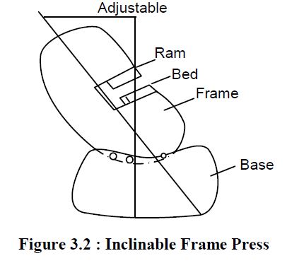
Inclinable Frame Press
Its frame is called inclinable due to its capability to tilt back up to some angle. It can be locked into any of its inclined position as shown in Figure. Its back is open to exit the scrap so it is also called the open back inclinable press.
Gap Frame Press
These presses have larger frame openings, which means a wide gap between its base and ram to accommodate larger workpieces. It also has longer beds, as shown in Figure.

Straight Side Press
These presses have straight side type frames which is preferred for presses having larger bed areas and high tonnage. This offers greater rigidity and capable of long strokes. The frame consists of vertical and straight sides so it is called straight side press.
Adjustable Bed Type Press
It is also called column and knee type press because it has a knee-type bed supported on its column-shaped frame. Its bed (knee) can be adjusted at any desirable height by moving it vertically up or down with the help of power screws. In this structure there is a slight lack of rigidity as compared to other structures. It is shown in Figure.

Open End Press
It has a solid type of vertical frame with all sides open. The driving mechanism is housed at the back and ram controlling mechanism at the front. It is easy to accommodate the workpiece and dies in this type of structure. It is identified as a light-duty machine.
Horning Press
It consists of a vertical frame, top of which overhangs towards the front. The overhanging portion serves for housing for driving mechanism and ram control. The frame consists of a front face as a work table called a horn.
3. According to the Position of Frame
Presses can also be categorized by the position of frame as described below.
Inclinable Frame
Already described.
Vertical Frame
Vertical frame type of press is already been discussed, it cannot be adjusted like the inclinable frame. Gap, adjustable bed, straight side, open-end, and honing presses are the example of vertical frames.
Horizontal Frame
It has a fixed frame in a horizontal position. It provides the facility of auto ejection of produced part and scrap due to gravity.
Inclined Frame
Like the inclinable frame, inclined frame press has an inclined frame but fixed, it cannot be adjusted to any other angle.
4. According to the Actions
According to the number of actions it can be categorized as a single action, double action or triple-action press. Here the number of actions is the same as the number of rams on the press.
5. According to Mechanism Used to Transmit Power to Ram
Crank Press
It consists of crankshaft driven by a flywheel, the rotary motion of the crankshaft is converted into reciprocating motion with the help of a connecting rod connected to ram.
Cam Driven Press
In this press, a cam is used to press the ram down words and suitably located springs restore the original position of ram when pressure applied is removed. This mechanism has a limitation of the size of the press.
Eccentric Press
In this press, the driving shaft carries an eccentric integral with it. One end of the connecting rod carried an attachment of revolving eccentric and its other end is connected to ram. As the eccentric shaft revolves, the offset between the eccentric center and the center of rotation of the shaft provides the required movement.
Knuckle Press
This press is driven with the help of a knuckle joint mechanism. The main advantage of this press is partial back thrust is transferred to the crankshaft, its major portion is transferred to the back crown which is capable to hear. This enables the application of this press for heavier jobs with high intensity of blows. These presses are recommended for coining, squeezing, extruding and embossing. They have a limitation of shorter stroke lengths.
Toggle Press
These presses work on toggle mechanism and used for double and triple action presses for driving the outer rams. However, the crankshaft drive is used for the inner ram. These are used for large draw dies, in which this mechanism actuates the blank holder whereas the punch is operated by the crank driven inner ram.
Screw Press
This is known as a power screw or percussion press. There is a vertical are like frame, its job forms a nut. There is a flywheel at the top of and engages the ram at its bottom. The flywheel is driven by a friction disc and the rotating screw lowers and raises the ram. The flywheel is accelerated by friction drive. Its total energy is expanded in striking the work, bringing it to a halt. The intensity of blow can be regulated by adjusting the height of the die. Higher the position of the die, lesser the speed of the flywheel and hence lower the intensity of blow. These presses have a limitation that the ram movement is slow so these are recommended for sheet metal work only.
Hydraulic Press
These presses have a piller type construction or carry the hydraulic cylinder at the top of the crown. These presses provide longer stroke than mechanical presses with adjustable intensity of blow. Their stroke length can also be adjusted with full tonnage. These are recommended for deep drawing, extruding and plastic molding.
Rack and Pinion Press
Rack and pinion driven presses are called rack and pinion presses meant for long strokes. The major advantage is the faster operation of this press due to the involvement of quick return motion. There are some limitations of this press. The load-bearing capability of a rack and pinion mechanism is very low so these are light-duty machines. Ram movement is slightly slower. These presses have very limited use nowadays.
6. According to Number of Drive Gears
The number of drive gears means the number of gears attached at the ends of the crankshaft, used to drive it. Smaller presses have the single drive and larger presses may be double drive crankshafts. Very large presses with longer beds carry long crankshafts. They have a risk of twisting. These crankshafts are provided with one driving gear at each end, these presses are named as twine drive presses. If a press carries two crankshafts each having a twin drive, such presses are called quadruple drive presses.
7. According to Number of Crankshaft in a Press
According to the number of crankshafts used in a press, these are directly classified as single crank (having one crankshaft) double crank (having two crankshafts).
Method of transmission of power from Motor to Crankshaft
The method used for transmission of power from the motor to crankshaft categorized presses into the following categories :
Direct Drive Press
In this case, power is directly transferred through gears pair. Smaller gear is mounted on the motor shaft, called pinion, its larger mating gear, mounted on the crankshaft. The larger gear also acts as a flywheel. The flywheel is attached to the crankshaft through the clutch and equipped with the facility of disengaging it as per the need. Such presses have shorter strokes and these are light-duty presses.
Flywheel Driven Presses
These presses consist no gears so also called “No geared presses”. For the transmission of power motor pulley is connected to flywheel driven crankshaft by Vee belt and pulley system. A clutch is used to engage or disengage the flywheel with the crankshaft. These presses are light-duty presses providing shorter and quicker strokes.
Single Geared Drive Presses
This press consists of a countershaft between motor shaft and crankshaft. The flywheel is mounted on the countershaft. Power is transferred from motor to flywheel (countershaft) through the „Vee‟ belt drive and then from countershaft to crankshaft through pinion and gear. Clutch is mounted between pinion and flywheel to disengaged the power transmission as per the requirements. In these presses there are two steps for rpm reduction and torque enhancement so these are heavy-duty mechanics with longer strokes.
Double Geared Drive Presses
In these types of presses an additional shaft named as the intermediate shaft is introduced between the countershaft mounted flywheel and the crankshaft of a single geared drive. Twin drive is possible in this case by having similar gear trains on other sides of two shafts. This provides a slow stroke with larger power.
8. According to the Purpose of Use
Some of the operations require low stroke strength and some lager stroke strength. In the same way requirements of the stroke length is different for different operations. So depending on power and stroke length presses are classified as given below depending on their suitability of performing different operations.
(a) Shearing press
(b) Seaming press
(c) Straightening press
(d) Punching press
(e) Extruding press
(f) Caining press
(g) Forging press
(h) Rolling press
(i) Bending press.
Read More : Press Machine Working – Die And Punch | Interview Question and Answers
MAIN PARTS OF A TYPICAL POWER PRESS MACHINE
Different types of presses have almost common types of main parts. These parts are described below.
Base
The all machine tool, the base is one of the parts of a press. It is the main supporting member for workpiece holding dies and different controlling mechanisms of the press. The size of the table limits the size of the workpiece that can be processed on a press. In case of some special presses the base carries mechanism for tilting the frame in any desirable inclined position too.
Frame
Frame constitute the main body of the press located at one edge of its base. It houses support for ram, driving mechanism and control mechanisms. Some of the press have a column-shaped frame.
Ram
This is the main operating part of the press which works directly during the processing of a workpiece. Ram reciprocates to and fro within its guideways with prescribed stroke length and power. The stroke length and power transferred can be adjusted as per the requirements. Ram at its bottom end carries punch to process the workpiece.
Pitman
It is the part that connects the ram and crankshaft or ram eccentric.
Driving Mechanism
Different types of driving mechanisms are used in different types of presses like a cylinder and piston arrangement in a hydraulic press, crankshaft and eccentric mechanisms in a mechanical press, etc. these mechanisms are used to drive ram by transferring power from the motor to ram.
Controlling Mechanisms
Controlling mechanisms are used to operate a press under predetermined controlled conditions. Normally two parameters are adjusted by controlling mechanisms length of stroke of ram and power of the stroke. Transfer of power can be disengaged with the help of a clutch provided with driving mechanisms as per need. In most of the presses controlling mechanisms is inbuilt with the driving mechanisms. Nowadays compute controlled presses are being used in which control is guided by the microprocessor. These presses provides reliable and accurate control with automation.
Flywheel
In most of the presses, driven gear or driven pulley is made of the shape of the flywheel, which is used for storing the energy reserve wire of energy) for maintaining a constant speed of ram when the punch is pressed against the workpiece. Flywheel is placed in the driving mechanism just before the clutch is a sequence of power transmission.
Brakes
Brakes are very urgent in any mobile system. Generally two types of brakes are used normal brake, which can bring the driven shaft to rest quickly after disengaging it from the flywheel. Other is emergency brakes which are provided as foot brakes to any machine. These brakes include power off switch along with normal stronger braking to bring all motions to rest quickly.
Balster Plate
It is a thick plate attached to the bed or base of the press. It is used to clamp the die assembly rigidly to support the workpiece. The die used in press working may have more than one part that is why the phrase die assembly is being used at the place of the die.
SPECIFICATIONS OF A PRESS MACHINE
Expressing the size of a machine (press) includes expressing each of the parameters pertaining to it quantitatively in appropriate units. Expressing size in the above-mentioned way is the specifications of the press. The following parameters are expressed as specifications of a press.
(a) Maximum Force: Maximum force that its ram can exert on the workpiece, this is expressed in tones and called tonnage. It varies from 5 to 4000 tonnes for the mechanical press. It may be up to 50,000 tonnes by a hydraulic press.
(b) Maximum Stroke Length: Maximum distance traveled by the ram from its top most position to extreme down position. It is expressed in mm. the stroke length is adjustable so different values that can be obtained between minimum and maximum of stroke length, these are also the part of specifications.
(c) Die Space: Total (maximum) surface area, along with (b d), of bed, base, ram base. This the area in which die can be maintained.
(d) Shut Height: Total opening between the ram and base when the ram is at its extreme down position. This is the minimum height of the processed workpiece.
(e) Press Adjustments: Different stroke lengths (already covered in point number 2). Different tonnage that can be set as per the requirement.
(f) Ram Speed: It is expressed as the number of strokes per minute. Generally it can be 5 to 5000 strokes per minute.
More Resources /articles
Machine Tool , Manufacturing Projects List - Abstract , Report
Machine Tool Articles , notes , Interview Que & Ans
Manufacturing Technology Notes , Articles
Mechanical Subjectwise Basic Concept Notes ,Articles
Related posts:
 Major Parts of mechanical press and its Function
  Slotter Machine – Types, Parts, Operations, Diagram, Specification
  Lathe Machine – Definition, Types, parts, Specifications
  Introduction To Mechanical Presses Used For Sheet Metal
  Press Forging – Process , advantages and Disadvantages
  Shaper Machine – Types, Parts, Working, Operations, Diagram
  FABRICATION OF PNEUMATIC CONTROLLED RIVETTING AND PUNCHING MACHINE
  Press Working – Die And Punch | Interview Question and Answers
One thought on “Press Machine – Types , Parts , Diagram , Specifications”
Leave a Reply
Recent Posts
Mechanical Engineering is an essential discipline of engineering encompassing many specializations, with each contributing its unique aspect to the dynamic and inventive nature of this field. With...
The Ram Lalla idol, which is installed at Ayodhya's Ram temple has many significant religious symbols from Hinduism. All 10 incarnations of Lord Vishnu are engraved on the idol. Notably, Lord Ram is...
I would like to learn more about how best you do to reduce oil spirage from the manual oil pressing machine.