
Pneumatic braking system | Construction and Working
Pneumatic or air braking system in automobile | Construction and working of pneumatic braking system
- A brake which uses air as a working fluid is known as pneumatic brake. The system actuated to apply this phenomenon is know as pneumatic brake system.
- An pneumatic brake system or a compressed air brake system is a type of friction brake for vehicles in which compressed air pressing on a piston is used to apply the pressure to the brake pad needed to stop the vehicle.
See also :
Introduction to Automobile Braking System- Types Of Brakes
Construction and working of Air Brake System used in Automobile
Construction of pneumatic braking system
- The simplest air brake system consists of
- An air compressor
- A brake valve
- series of brake chambers at the wheels
- unloader valve
- A pressure gauge and a safety valve
- and an air reservoir.
- These are all connected by tubes.
- Some air braking systems may have additional components such as
- stop light switch
- low pressure indicator
- An air supply valve to supply air for tyre inflation
- A quick release air quickly from the front brake chambers when the brake pedal is released
- A limiting valve for limiting the maximum pressure in the front brake chambers and a relay valve to help in quick admission and release of air from the rear brake chambers.

working of pneumatic braking system

Working of pneumatic braking system
- The air compressor operated by the engine forces air at a pressure of 9-10 kscm (kilo standard cubic meters) through the water and oil separator to the air reservoir.
- The air pressure in the reservoir is indicated by a pressure gauge.
- The reservoir contains enough compressed air for several braking operations. From the reservoir the air is supplied to the brake valve.
- As long as brake pedal is not depressed, brake valves stop the passage of air to brake chambers and there is no braking effect.
- When the brake pedal is depressed, the brake valves varies its position and compressed air is admitted into the wheel brake chambers.
- In the chambers the air acts upon flexible diaphragms, moves them the pushes out the rods connected with the levers of the brake gear cams.
- The cams turn and separate the shoes thus braking the wheels.
- When the brake pedal is released, the supply of compressed air is cut off from the brake chambers and they are connected to the atmosphere.
- The pressure in the chambers drops, the brake shoes are returned to their initial position and the wheels run free.
- The brake valve is equipped with a servo mechanism which ensures that the braking force on the shoes is proportional to the force applied to the pedal.
- Besides the valve imparts a relative reaction to the movement of the pedal so that the driver can sense the degree of brake application.
Related posts:
 Air Braking System | Components , Working Principle , Application
  Air Brake System – Parts, Working, Diagram, Principle, Advantages
 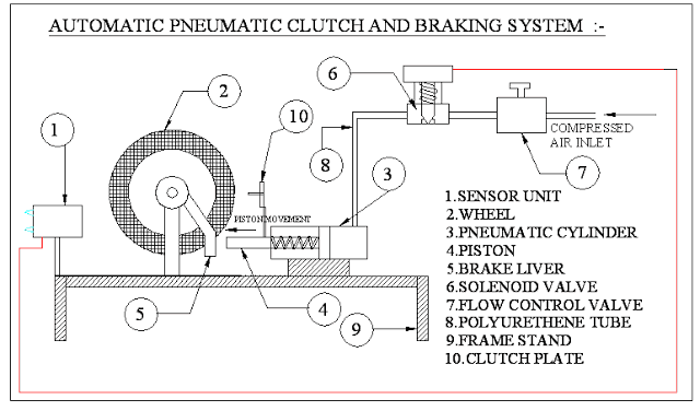 Automatic Pneumatic Clutch and Braking System
  Master Cylinder | Types , Working Principles and Applications
  Intelligent Braking System in Four Wheeler – Mechanical Project
  Fabrication Of Pneumatic braking System report Download
  Drum Brake : Components , Types and Working Principle
  Hydraulic Brakes – Parts, Working, Diagram, Advantages and Disadvantages
Recent Posts
Velocity Ratio of Belt Drive – Formula, Explanation and Calculation
Velocity Ratio of a Belt Drive – Formula, Explanation and Calculation A belt drive is a mechanical power-transmission system used to transfer rotary motion from one shaft to another. It generally...
AI in AutoCAD and SolidWorks: Complete Guide for Mechanical Engineers (2026)
Artificial Intelligence (AI) is revolutionizing almost every engineering industry, and Computer-Aided Design (CAD) software is no exception. Mechanical engineers, product designers, architects, and...