Table of Contents
Air Braking System | Components , Working Principle , Application
“Brakes are as important as an engine for an automobile” very rightly said as if we require engine to run a vehicle than we also requires brakes to stop it, This statement also resembles with the Newton’s first law, we all are familiar with. As we know now a day in light vehicles we use hydraulic brake system to stop or decelerate the vehicle, But the questions arises, Is the hydraulic brake system effective when it comes to heavy vehicles ? If not then, What do we need to stop or decelerate the heavy vehicles like buses and trucks ? Let’s hunt the answers.
Read more :
Construction and working of Air Brake System used in Automobile![]()
Types of Brakes | Different types of Braking System![]()
Air brake system is a type of braking system generally used in heavy commercial vehicles or vehicles which require some really powerful and efficient braking system. It is a kind of friction brake where instead of hydraulic-fluid, air is used as the compression media for brake pads.
Pneumatic air brake system is usually used in heavy vehicles like buses and trucks.
Air brakes were invented by George Westinghouse for use in trains. After having proved its caliber in trains, air brakes were later adapted to be used in heavy vehicles. The safety and braking confidence that air brakes provide to heavy vehicles are vouched for till day.
There is a need of different braking systems due to the following reasons-
- As the load over light vehicle and heavy vehicle varies the brake force required to stop the heavy vehicle is far more than that of light vehicle, so the heavy vehicles should be equipped with a braking system that can provide the enough brake force that can stop or decelerate the vehicle.
- When we talk about light weight vehicles, hydraulic brakes provides more than enough brake force to stop or decelerate the vehicle due to its short dimension but when it comes to the heavy vehicles which are large in size the effectiveness of hydraulic brake system is the great concern.
- As the fluid is used to press the piston in hydraulic braking system the safety is the great concern as if there is any leak in the components of the hydraulic system the efficiency of the braking is readily reduced or even lost completely, since air is always available so the brake failure due to leakage is the less concern in air braking system.
- The components(master cylinder, brake lines etc.) size of the hydraulic brake system increases with the increase in the size of the vehicle which in turn makes it very complex to install, which is not a problem with air brake system.
- Due to the safety measures like brake failure and efficiency, Government has made it compulsory for heavy vehicles like buses and trucks to use air brake system.
So due to these above mentioned reason on March 1872 George Westinghouse introduced air braking system for the braking system in railways due to its fail-safe feature.

COMPONENTS
1. Air compressor-
It is the compressor that pumps air from atmosphere to the air storage tank and is driven by the engine through belt drive.
2. Air compressor governor-
It is the governing device used in air brake system that controls the compression pressure of the air that is pumped to the air storage tank through air compressor.
3. Air dryer-
It is the device used to remove moisture content from the air coming from the atmosphere to prevent the lines and air storage from water condensation that can cause brake failure such as during winters due to the freezing of that condensed water.
4. Air storage (reservoir)-
It is the tank that is used to store the compressed air sent by the compressor, this storage always has enough amount of compressed air so that the brakes can be applied several time and also prevents the brake failure when the air compressor shows malfunctioning.
5. Brake pedal-
It is the mechanism that is operated by the driver and is used to actuate the brakes in order to stop or decelerate the vehicle. Brakes when pressed pushed the compressed air which in turn applies brakes to the moving tyre.
6. Dirt collector-
It is the device that is placed inside a brake pipe line at place where a branch is separated and taken off to the triple valve which removes dirt from the air before sending it to the triple valve
7. Brake cylinder or Brake chamber-
It is the device that consists of a cylinder and piston over which the compressed air pressure is applied in order to push brake pads which in turn makes frictional contact with the disc or drum in order to stop or decelerate the vehicle.
8. Brake valve or Triple valve-
The actuation and release of brake requires continuous release and building of pressure inside the brake lines and brake cylinder according to the motion of the brake pedal this is done by the triple valve used in air brake system.
9. Brake drums –
Brake drum is the component through which the brake force due to frictional contact between brake pads and drum lining is transferred to the wheel in order to stop or decelerate the vehicle, Outer surface of the brake drum consisting of drum lining rotates with the wheel and the inner part consisting of brake shoes stays in its state of rest when the brake pedal is not pressed.
Note – Usually brake drums are used in air brake system but with suitable arrangement disc brake can also be used in air brake system.
WORKING PRINCIPLE
A typical air brake system configuration for a heavy vehicle consists of service brakes, parking brakes, a control pedal and an air storage tank. Parking breaks in this configuration consist of a set of disc or drum brakes held in lock position by a spring mechanism. Air pressure is then required to release the parking brake and set the vehicle in motion. In case of service brakes which are used for regular operation of the vehicle, a pedal is pushed for stopping or engaging and disengaging the brake.

Generally, a pressure of 6.8 to 8.2 bars is used for this kind of application. A majority of heavy commercial vehicles use drums with air brake systems although now the usage of disc brakes are also catching up. Every vehicle fitted with air brakes has a pressure gauge mounted on the dashboard and in clear line of view of the driver, this enables the driver or the operator of the vehicle to be completely aware of the operational pressure in the compressor. Also, proper systems and safety mechanisms are in place which alerts the driver or operator if there is a malfunction or a sudden drop in operating pressure. As an emergency fail-safe mechanism in case of an extreme sudden drop in the air pressure, the spring operated parking brakes are immediately engaged putting the vehicle to a safe stop.
The basic principle of an air brake system is similar to any other type of braking system, the only differentiating factor being use of compressed air in place of hydraulic fluids.
So in principle it’s just a conventional braking system.
Supply System: The heart of any air brake system is the compressor, Compressor is the device which generates and in a way regulates the flow of compressed air in the system. The compressor is powered by the engine directly and uses the common lubricant available with the engine.
Compressed air is pushed through a cooling coil and into an air dryer. From here the air is stored in a reservoir tank for use. Reservoir tank is connected with an intricate network of circuits for front brakes, rear brakes, and the parking brakes. The supply system also contains the drain valve, pressure limiting valve, and the safety valve.
Control System: Control system consists broadly of service break circuit, parking brake circuit and the trailer brake circuit (if applicable). Service break circuit consists of two individual break circuits each for front and the rear brake. Both these circuits are connected to their special reservoirs for added safety in case the master reservoir fails.
Parking break circuit is connected to a spring mechanism in which the air pressure is used to keep the spring in unlocked position. A drop in pressure of this circuit results in engaging of parking brakes. The trailer brake system has its own lines for operation and is used when there is a trailer attached to the vehicle. It has a supply line and a control line. The supply line is fed by the master reservoir and control line gets its signal from the service break system for better braking.
When the driver of a vehicle presses the brake pedal in order to stop or decelerate the vehicle the following processes takes place-
1. When the driver starts the engine the brake compressor starts as it is driven by the engine which in turn starts compressing the atmospheric air and through the compressor governor this compressed air with optimum pressure is sent to the compressed air reservoir which always has some amount of air stored from the previous cycle.
2. When the driver presses the brake pedal the outlet valve of the triple valve closes and inlet valve opens up which in turn gives passage to the compressed air from the reservoir to pass through the brake lines of the system.
3. This compressed air flowing through the brake lines is then transferred to the brake cylinder which has piston inside it.
4. When the compressed air applies pressure over the piston inside the brake chamber, piston moves away from its original position which converts this pneumatic energy into the mechanical energy.
5. On the wheel end of the brake cylinder, brake drums are placed inside which there is a housing of the mechanical actuator like springs or slacks having brake pads at its outer end.
6. Due to the movement of piston because of the pressure applied by the compressed air, The mechanical actuator inside the brake drum expands which in turn pushes the brake pads in outward direction in order to make frictional contact with the rotating drum lines.
7. With this frictional contact between brake pads and rotating drum lines brakes are applied to the wheels in order to stop or decelerate the vehicle.
APPLICATIONS
Due to its property of preventing brake failure air brakes systems are widely used in various vehicles but in heavy vehicles like trucks and buses due to the government vehicle regulations air brake system is mandatory.
1. It is used in railways
2. All the trucks and busses on the road today use air brake systems, few from them are.
- Volvo 9400PX buses.
- Bharat Benz 3123R truck.
- trucks having multiple trailers,
- high-speed long-haul buses,
- vehicles of military utility and
- semi-trailers
More Resources /articles
Automobile Engineering Parts and System Notes , Article
Automobile Trends , News articles , Notes
Mechanical Subjectwise Basic Concept Notes ,Articles
Latest seminar topic index - Report ,PPT Download
Related posts:
 Air Brake System – Parts, Working, Diagram, Principle, Advantages
  Drum Brake : Components , Types and Working Principle
  Pneumatic braking system | Construction and Working
  Electric Parking Brake (EPB) | Components , Working Principle and Types
  Types of Brakes | Different types of Braking System
  Braking System : Function , Classification ,Electronics Brakes
 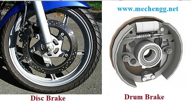 Introduction To Brakes and Different Types Of Brake | Function Of Braking System
  Windows air Conditioning | Working , Components and Application
Recent Posts
Mechanical Engineering is an essential discipline of engineering encompassing many specializations, with each contributing its unique aspect to the dynamic and inventive nature of this field. With...
The Ram Lalla idol, which is installed at Ayodhya's Ram temple has many significant religious symbols from Hinduism. All 10 incarnations of Lord Vishnu are engraved on the idol. Notably, Lord Ram is...