Table of Contents
Check Valve – diagram ,Symbol, Types Of Check valve
In this articles we will learn about check valve, used for hydraulic and pneumatic circuits . Briefly information is given about check valve types, check valve diagram ,symbol used for check valve .
Check Valve
The simplest DCV (Direction Control Valve ) is a check valve. A check valve allows flow in one direction, but blocks the flow in the opposite direction. It is a two-way valve because it contains two ports. Figure shows the graphical symbol of a check valve along with its no-flow and free-flow directions.
Symbol Of Check Valve:

Types Of Check Valves:
The various types of check valves are available for a range of applications. These valves are generally small sized, simple in construction and inexpensive. Generally, the check valves are automatically operated. Human intervention or any external control system is not required. These valves can wear out or can generate the cracks after prolonged usage and therefore they are mostly made of plastics for easy repair and replacements.
Classification of check valves used in hydraulics and pneumatic are as follows :
- Ball type Check valve
- Poppet check valve
- pilot operated check valve
- shuttle valve
Ball type Check valve
In Fig., a light spring holds the ball against the valve seat. Flow coming into the inlet pushes the ball off the seat against the light force of the spring and continues to the outlet. A very low pressure is required to hold the valve open in this direction. If the flow tries to enter from the opposite direction, the pressure pushes the ball against the seat and the flow cannot pass through.

Poppet check valve
Figure provides two schematic drawings showing the operation of a poppet check valve. A poppet is a specially shaped plug element held on a valve seat by a light spring. Fluid flows through the valve in the space between the seat and poppet. In the free flow direction, the fluid pressure overcomes the spring force. If the flow is attempted in the opposite direction, the fluid pressure pushes the poppet in the closed position. Therefore, no flow is permitted

Advantages of a poppet valve
- Virtually zero leakage in closed position.
- Poppet elements do not stick even when left under pressure for long periods.
- Fast, consistent response time: typically 15 ms.
Disadvantages of a Poppet Valve
- Axial pressure balance is impossible and considerable force may be needed to open the poppet against the flow at a high pressure. This limits valves that have direct mechanical actuation to low flow duties.
- Generally individual poppets are required for each flow path that significantly increases the complexity of multi-port valves.
- Lapping and super finishing of valves add cost.
Pilot-Operated check Valve
A pilot-operated valve along with its symbol is shown in Fig.. This type of check valve always permits free flow in one direction but permits flow in the normally blocked opposite direction only if the pilot pressure is applied at the pilot pressure point of the valve. The check valve poppet has the pilot piston attached to the threaded poppet stem by a nut.
The light spring holds the poppet seated in a no-flow condition by pushing against the pilot piston. The purpose of the separate drain port is to prevent oil from creating a pressure build-up at the bottom of the piston. The dashed line in the graphical symbol represents the pilot pressure line connected to the pilot pressure port of the valve. Pilot check valves are used for locking hydraulic cylinders in position.

Shuttle Valve
A shuttle valve allows two alternate flow sources to be connected in a one-branch circuit. The valve has two inlets P1 and P2 and one outlet A. Outlet A receives flow from an inlet that is at a higher pressure. Figure 1.5 shows the operation of a shuttle valve. If the pressure at P1 is greater than that at P2, the ball slides to the right and allows P1 to send flow to outlet A. If the pressure at P2 is greater than that at P1, the ball slides to the left and P2 supplies flow to outlet A

One application for a shuttle valve is to have a primary pump inlet P1 and a secondary pump inlet P2 connected to the system outlet A The secondary pump acts as a backup, supplying flow to the system if the primary pump loses pressure. A shuttle valve is called an “OR” valve because receiving a pressure input signal from either P1 or P2 causes a pressure output signal to be sent to A. Graphical symbol of shuttle valve is shown in Fig.
Related posts:
 Pressure Control Valve- Types , Symbol ,Application
 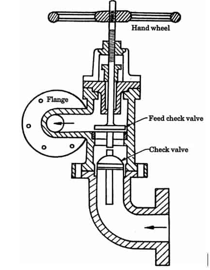 Feed Check Valve Diagram ,Working | Boiler Mounting and Accessories
  Pressure Relief Valve – Diagram , Working
  Safety Valve | Function ,types, Construction ,Working
  Types Of Valve Used In Industries and Plumbing
  Double acting Cylinder | Diagram , types , Symbol
Recent Posts
AI in AutoCAD and SolidWorks: Complete Guide for Mechanical Engineers (2026)
Artificial Intelligence (AI) is revolutionizing almost every engineering industry, and Computer-Aided Design (CAD) software is no exception. Mechanical engineers, product designers, architects, and...
Aluminium Alloys: Types, Composition, Properties, Heat Treatment & Applications
Introduction Aluminium is one of the most widely used engineering materials because of its lightweight, corrosion resistance, excellent thermal conductivity, and good machinability....