Following are the Devices which produce mechanical advantages .
Lever:
A lever is a machine consisting of a beam or rigid rod pivoted at a fixed hinge, or fulcrum. A lever is a rigid body capable of rotating on a point on itself. On the basis of the location of fulcrum, load and effort, the lever is divided into three types. It is one of the six simple machines identified by Renaissance scientists. A lever amplifies an input force to provide a greater output force, which is said to provide leverage. The ratio of the output force to the input force is the mechanical advantage of the lever.
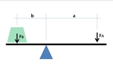
Mechanical Advantages -Lever
The beam shown is in static equilibrium around the fulcrum. This is due to the moment created by vector force “A” counterclockwise (moment A*a) being in equilibrium with the moment created by vector force “B” clockwise (moment B*b). The relatively low vector force “B” is translated in a relatively high vector force “A”. The force is thus increased in the ratio of the forces A : B, which is equal to the ratio of the distances to the fulcrum b : a. This ratio is called the mechanical advantage. This idealised situation does not take into account friction.
Pulley:
Pulley systems are an important part of many machines. In this Investigation, you will be testing factors that might influence the actual mechanical advantage of pulley systems.
Mechanical Advantages- Pulley
A single fixed pulley, like the one in Figure 1(a), has an ideal mechanical advantage of 1 since the effort force (120 N) is equal to the load force (120 N). However, in the single movable pulley (Figure 1(b)), half of the load is supported by the rope attached to the ceiling. The other half is supported by the free end of the rope, where the effort force is applied. Therefore, the effort force needed to move the load is only one-half the load force, or 60 N. The mechanical advantage of this pulley is 2. A simple way to determine the ideal mechanical advantage to a pulley system is to count the number of lengths of rope between pulleys that support the load.
In Figure 1(a), only one segment of rope supports the load. Therefore, the mechanical advantage is 1. In Figure 1(b), two segments of rope support the load, so the mechanical advantage is 2.
A block and tackle of multiple pulleys creates mechanical advantage, by having the flexible material looped over several pulleys in turn. Adding more loops and pulleys increases the mechanical advantage.
Wheel and Axle :
Wheel and axle motion (e.g. screwdrivers, doorknobs): A wheel is essentially a lever with one arm the distance between the axle and the outer point of the wheel, and the other the radius of the axle. Typically this is a fairly large difference, leading to a proportionately large mechanical advantage. This allows even simple wheels with wooden axles running in wooden blocks to still turn freely, because their friction is overwhelmed by the rotational force of the wheel multiplied by the mechanical advantage.
Screw:
A screw is essentially an inclined plane wrapped around a cylinder. The run over the rise of this inclined plane is the mechanical advantage of a screw.
The theoretical mechanical advantage for a screw can be calculated using the following equation:
MA= (3.14 x dm) / l
Where:
dm = the mean diameter of the screw thread
l = the lead of the screw thread
Note that the actual mechanical advantage of a screw system is greater, as a screwdriver or other screw driving system has a mechanical advantage as well.
Inclined plane: MA = length of slope ÷ height of the slope
Sachin is a B-TECH graduate in Mechanical Engineering from a reputed Engineering college. Currently, he is working in the sheet metal industry as a designer. Additionally, he has interested in Product Design, Animation, and Project design. He also likes to write articles related to the mechanical engineering field and tries to motivate other mechanical engineering students by his innovative project ideas, design, models and videos.
Mechanical Engineering is an essential discipline of engineering encompassing many specializations, with each contributing its unique aspect to the dynamic and inventive nature of this field. With...
The Ram Lalla idol, which is installed at Ayodhya's Ram temple has many significant religious symbols from Hinduism. All 10 incarnations of Lord Vishnu are engraved on the idol. Notably, Lord Ram is...


 Mechanical Advantages | Definition, Formulas, Ideal And Actual Advantages
  Mechanical Drives- Belt, Chain, Gear | Advantages and Disadvantages
  10 Power Transmission Devices used in Mechanical Engineering
  Front Engine Front Wheel Drive | Diagram , Advantages
  Front Engine Rear Wheel Drive | Advantages and Disadvantages
  Advantages and Disadvantages of Front wheel Drive
  What is Wheel bearing -Different layout Of Wheel Bearing
  DESIGN OF HALF – SHAFT AND REAR WHEEL HUB ASSEMBLY OF A RACE CAR